
HOW TO REVERSE ENGINEER CAR PARTS WITH DIGITAL CALIPERS AND SHAPR3D
So you want to reverse engineer a discontinued car part from scratch, but you're not sure how to turn a handful of caliper measurements into a clean 3D printable file?
Here's the exact steps you'll need:
Measure the part with digital calipers
Sketch dimensions on paper before you open CAD
Build the base shape in Shapr3D using those measurements
Shell the part, sketch and extrude the clips
Add fillets and chamfers to match the original
Export as STL, slice, print in ASA, and install
HOW WE STARTED MAKING 3D PRINTED PARTS
Finding replacement parts for a 1984 Datsun 280ZX is nearly impossible.
The car is 40+ years old. Most OEM plastic parts are discontinued, cracked, or so brittle that they break the moment you touch them.
3D printing changes that entirely — but only if you can learn how to design the car part yourself.
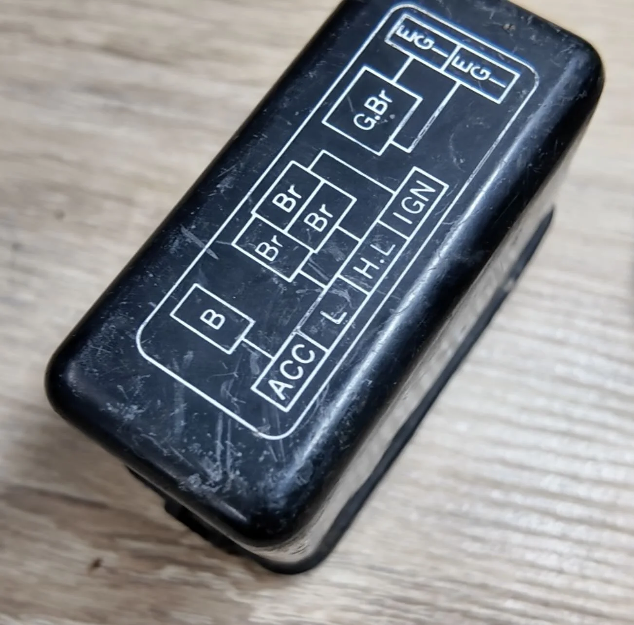
The relay cover on our 280ZX is a simple rectangular enclosure with retention clips. No complex curves or shapes. A perfect car part to reverse engineer and 3d print.
WHY DIGITAL CALIPERS ARE THE RIGHT TOOL
Most parts you'll reverse engineer on a project car — relay covers, brackets, trim clips, delete plates — are simple.
That's the caliper's sweet spot.
A basic set of digital calipers gives you sub-millimeter accuracy for under $30.
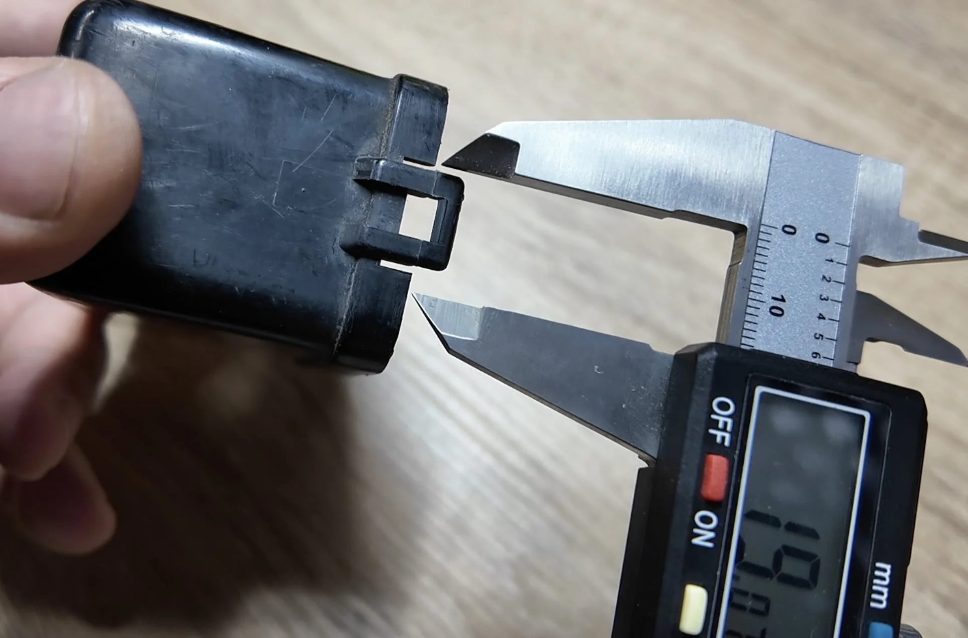
For parts without complex organic curves, that's the only measuring tool you need.
💡 PRO TIP: Before you open CAD, sketch the relay cover on paper from multiple angles and write every measurement next to the corresponding feature. The paper sketch is your build plan. Having it in front of you while you model eliminates remeasuring.
HOW TO TAKE MEASUREMENTS FOR CAD
Start with the big three: outer width, outer length, overall height.
Then work into the details: wall thickness, clip width, clip height, lip overhang depth, and any center cutout dimensions in the clips.
Set your CAD units to millimeters before measuring and sketching anything. Mixing units mid-build is how you end up printing a part that's 2.54x the correct size.
❌ Don't round your measurements to the nearest whole number. If your caliper reads 12.4mm, type 12.4mm — not 12.
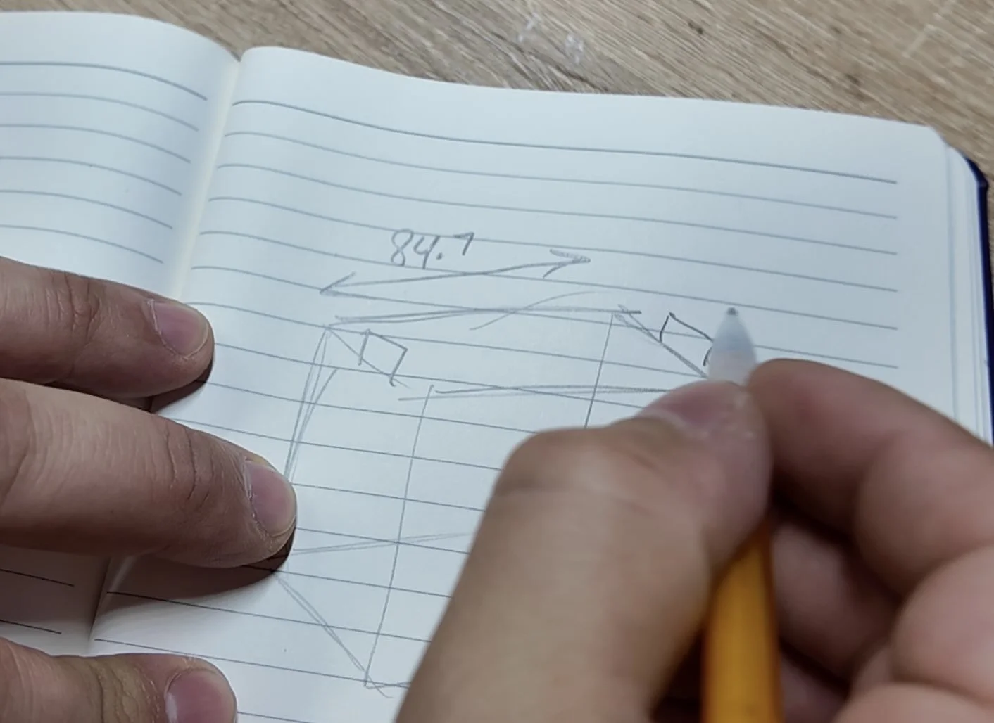
I also like to sketch the basic shape and record the measurements taken down on paper. This will make the next step much easier.
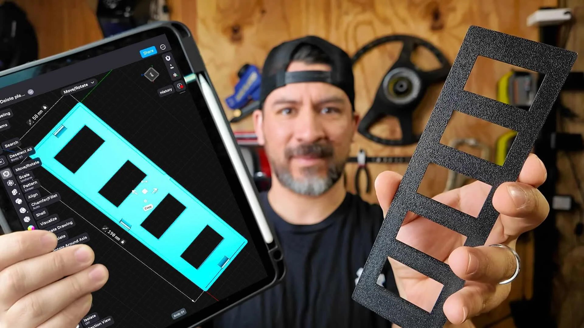
HOW TO BUILD THE BASE SHAPE IN SHAPR3D
Download Shaper3D. It’s my favorite CAD software because it’s intuitive and works on an iPad with an Apple Pencil.
Use affiliate code ALLABOUTTHEBUILD10 for 10% off
Open Shapr3D and tap the top face of the orientation cube to get a top-down view of the XY plane.
Dimensions don't matter yet.
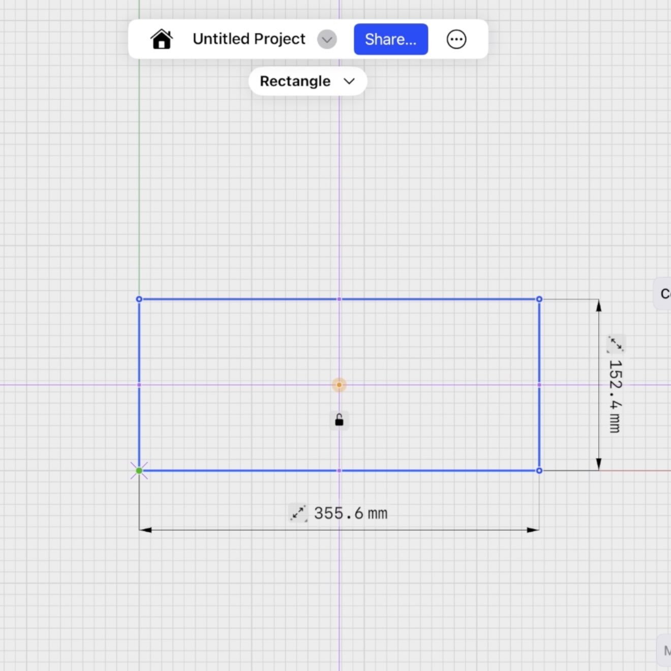
Now click each dimension value on your sketch and type in your measured width and length. The rectangle locks to those values.
Shapr3D automatically triggers the extrude function. Type in the measured height.
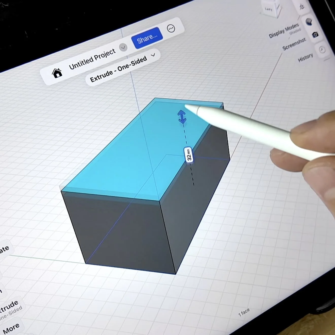
That's your base body. Three inputs, one solid.
HOW TO HOLLOW OUT THE PART AND BUILD THE OUTER LIP
For an engine bay relay cover in ASA, 2mm wall thickness is the target.
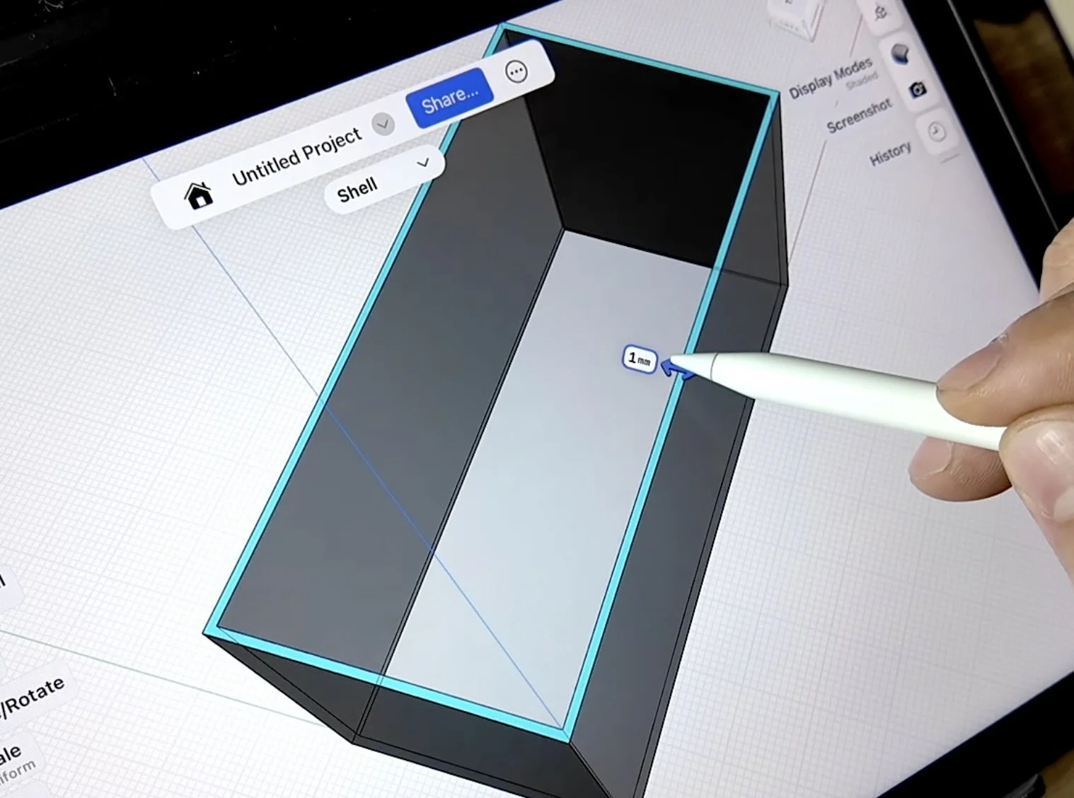
Thin enough to keep weight down, thick enough to handle heat cycling without cracking at the corners.
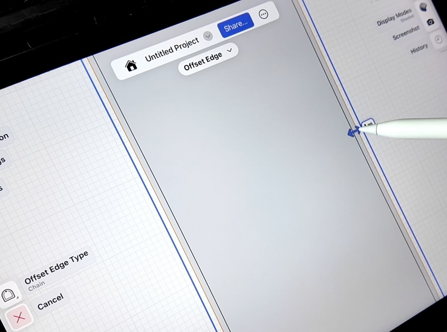
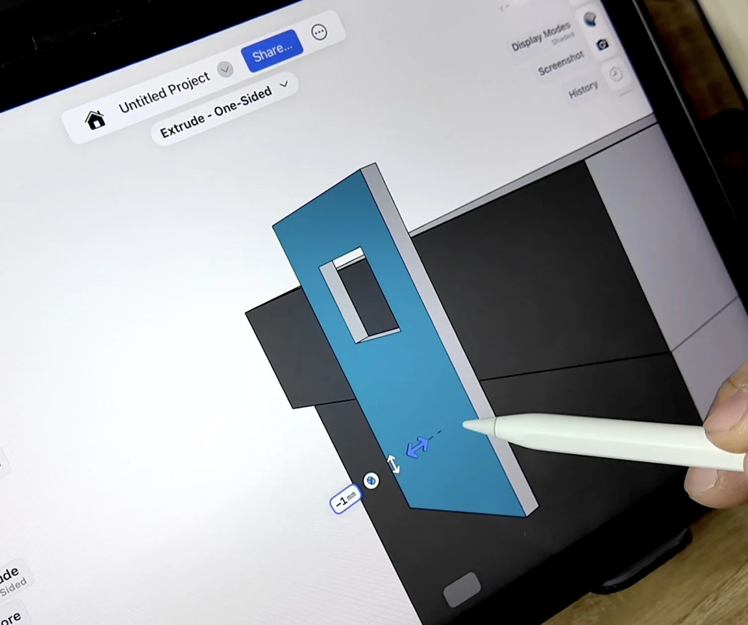
Select the offset shape, extrude upward to measured lip height, then drag slightly downward so the lip seats against the cover body.
If the lip floats above the base, it flexes under engine vibration and eventually cracks at the junction.
HOW TO SKETCH AND EXTRUDE THE RETENTION CLIPS
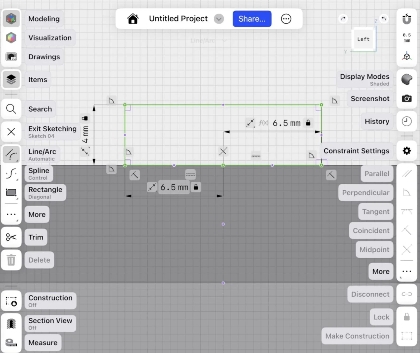
Switch to the left-hand view using the left orientation cube.
Sketch the clip profile starting from center. Divide the clip length by two to find the midpoint, then sketch each half symmetrically.
Then just extrude both clips outward.
If there's a gap at the base where the clip meets the cover, select the back face and extrude it toward the body to close it out.
💡 PRO TIP: Toggle the Items Tray to hide sketches that are in the way of face selection. If you delete instead of hide, you lose the geometry reference.
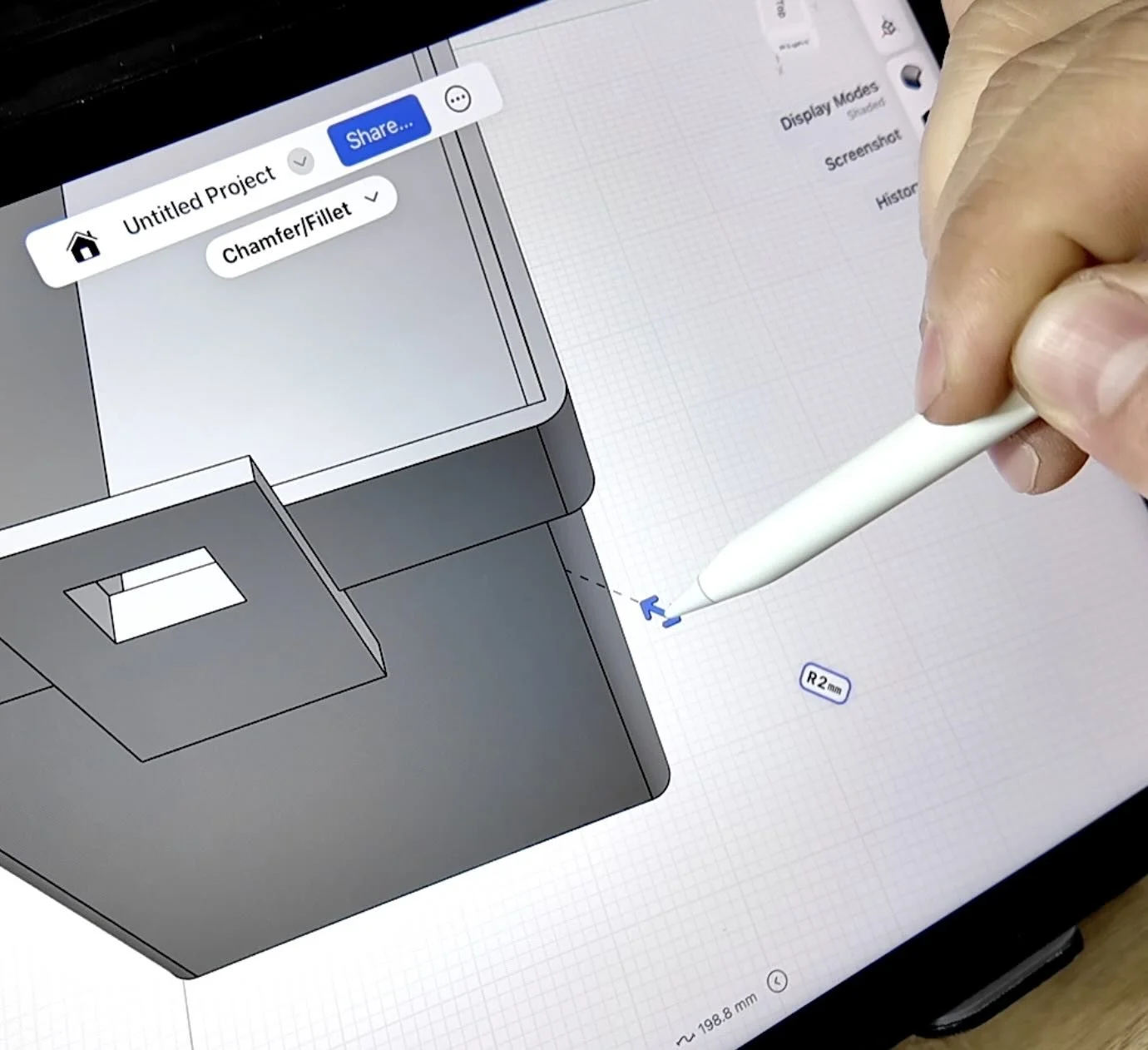
HOW TO ADD FILLETS AND CHAMFERS
Match the inner corners to the same or slightly tighter radius.
Tight inner fillets print cleaner than wide ones — less chance of under-extrusion in concave corners.
For edges below the clip overhangs: select the edge and push inward to chamfer rather than fillet.
💡 PRO TIP: A 45° chamfer on an overhanging edge eliminates the need for supports entirely on that feature. In ASA, unnecessary supports mean extra post-processing and risk of surface damage when you pull them.
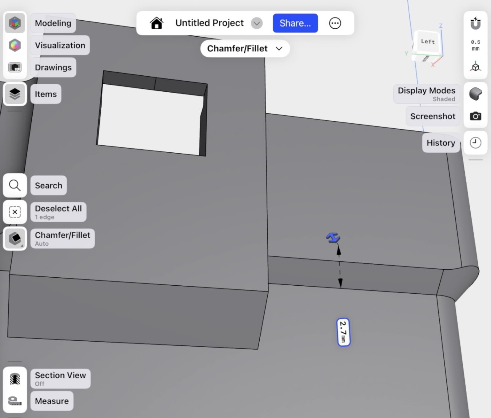
Hit the top corners of the clips with a matching chamfer. Sharp top corners on clips crack faster under repeated removal and installation.
HOW TO 3D PRINT THE RELAY COVER
Export as STL from Shapr3D. Import into Bambu Studio or Orca Slicer.
Run a preview — check the underside of the clips for any overhang that would require supports.
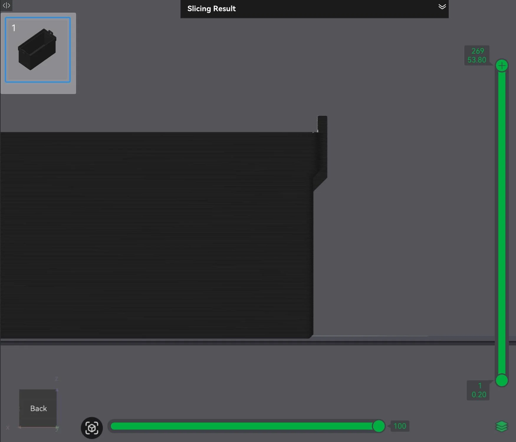
With the chamfers in place, not many supports shouldn't be needed.
Why ASA for an engine bay part: ASA handles up to 220°F, is UV resistant, and doesn't absorb moisture the way ABS does.
Based on relay cover location, which is far enough from the engine 220°F should be sufficient.
Pro Tip: If your part gets closer to the engine or touches hot parts like a radiator hose, then you’ll need to use PC filament or nylon based filament. Our 3d printing car parts filament guide can help you pick the right filament.
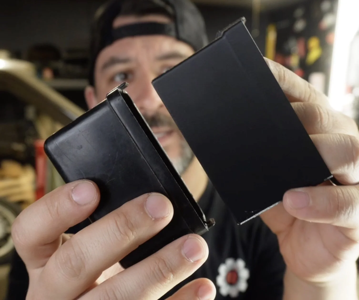
The printed clips came out slightly thicker than the original — that's intentional.
The original clips are 40 years old and brittle.
The printed version has controlled flex that the injection-molded plastic lost decades ago. They seat cleanly and hold firm under vibration.
Need more help?
Learn how to design and 3D print all in one day with an on-demand workshop.
Design 3d Printed Car Parts That Match Your Exact Build.
One afternoon. No complex software. Parts that fit your build perfect.
This workshop finally made designing 3d printed car parts feel doable. I had a replacement part ready for my project car in a few hours.
Instant Access, Risk Free Money Back Guarantee